TT Distribution System Regarding Grounding and Fault Protection
An important element in protecting humans (as well as property and animals) from the effects of electric current is the grounding of the system—this involves the grounding of the point of the electrical supply system and the grounding of exposed conductive parts.
Grounding the point of the electrical supply system (e.g., the 20/0.4 kV transformer substation that supplies power to a building) is an important element in protecting humans (as well as property and animals) from the effects of electric current. Similarly, grounding exposed conductive parts is also crucial. Exposed conductive parts (e.g., the casing of a motor) are normally not under voltage, but in the event of a fault, if a phase conductor comes into contact with the casing, it can become dangerous to touch.
Depending on the connection of the grounding system, the following power supply systems are allowed:
- TN
- TT
- IT
The type of allowed supply system is determined by the electricity distributor in their approval for connection to the grid. This approval is issued before the building permit is granted, and both designers and electrical installation contractors must adhere to it. In this article, I will focus on the TT supply system, which is commonly used in residential buildings.
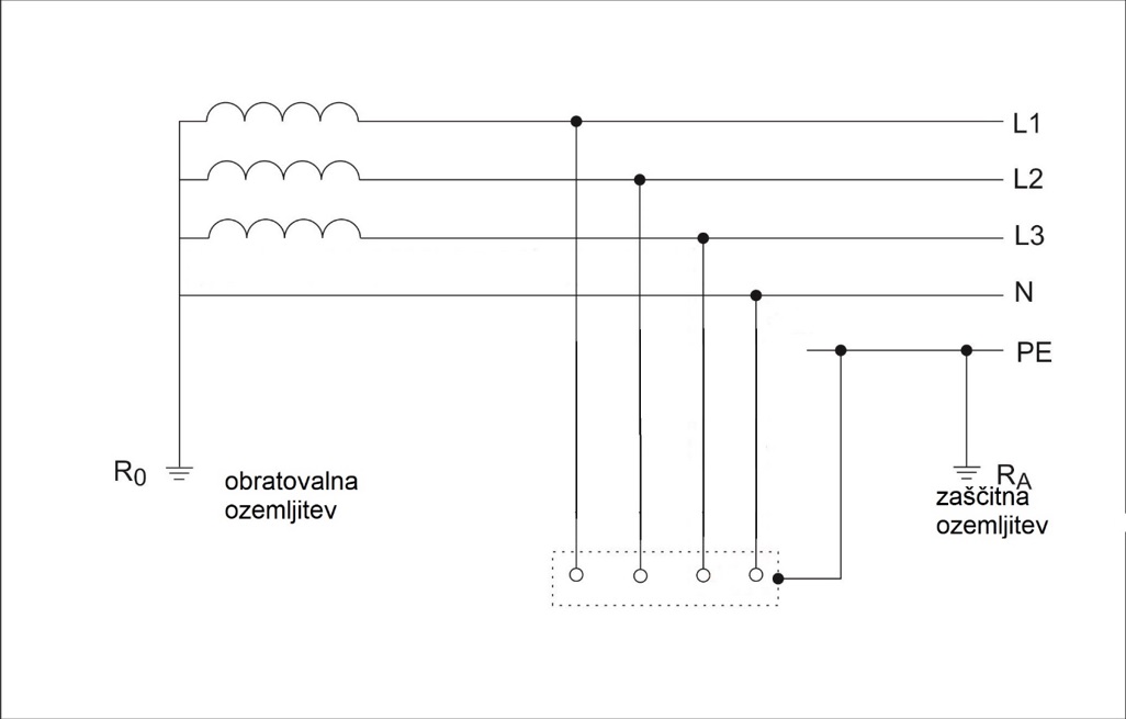
The first letter in the designation indicates the relationship of the power system to the ground; the letter "T" signifies that the neutral point of the transformer (the star point of the low-voltage winding of the three-phase transformer) is directly connected to the ground. This connection is typically made with a galvanized strip shaped into two rings and four arms. This grounding is located in the earth below or around the 20 kV/0.4 kV transformer substation at an appropriate depth. The second letter represents the relationship of exposed conductive parts of the electrical installation (e.g., the casings of electrical devices) to the ground. The second letter "T" indicates that exposed conductive parts are directly grounded, independent of the grounding of the power system (see Figure 1).
The TT grounding system is characterized by the fact that the operational grounding of the transformer substation is separate from the protective grounding, which is located in the ground or foundation of the building. The neutral point of the power system—the star point of the transformer—is grounded directly.

Figure 1: TT Power System Grounding
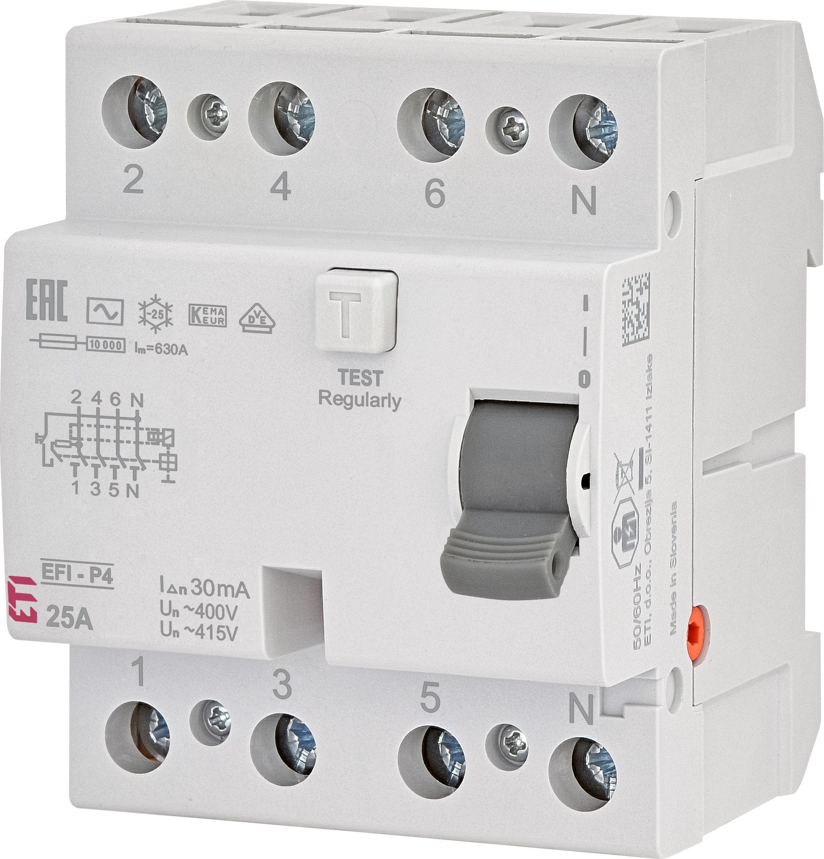
In the TT system (Figure 1), protection by automatic power disconnection is typically carried out using a residual current device (RCD). Figure 2 shows an example of a 25/0.03 A RCD.

Figure 2: 25 A/0.03 A RCD

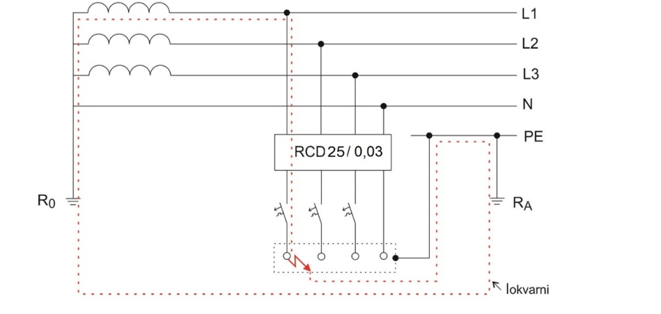
Figure 3: 4-pole RCD in the TT power system (principle of fault current flow)
Since in the TT system the RCD serves as protection against electric shock through automatic disconnection in electrical installations, let's try to explain this. The RCD is always activated by a current that occurs due to a specific fault. In the TT power system (Figure 3), in the event of a fault on an individual device or load (e.g., a live conductor comes into contact with the casing of an electric motor, which could be very dangerous for the user), the fault current flows through the motor casing via the protective conductor (PE conductor), through the protective grounding (RA) at the building, then through the earth to the operational grounding (RO) of the transformer substation, then through the low-voltage winding of the transformer and via the phase conductor (through the low-voltage network and the low-voltage installation itself) to the load. This constitutes the electrical circuit for the fault current. All metal casings of electrical devices are grounded with a protective conductor, whose insulation is green-yellow. In the RCD, an imbalance in the electrical current occurs, as the sum of the incoming and outgoing currents is not equal, and the RCD disconnects within 30 ms, which is crucial for human safety. This current difference is known as the residual current. If the residual current exceeds the value needed to trigger the RCD, the RCD will disconnect the circuit. In Figure 3, a four-pole RCD (40 A/0.03 A) with a residual current (IΔn) of 0.03 A is shown. In this case, the RCD will disconnect between 0.015 A and 0.03 A, or between 15 and 30 mA, if it is a standard RCD (AC type). In our example, with a 30 mA RCD, we also have protection against direct contact, as if we were to accidentally touch a live phase conductor, the RCD would limit the current passing through the human body to less than 30 mA, which according to theory is not life-threatening.
Figure 3 also illustrates why an RCD is typically always present in the TT system. It is very difficult to achieve that a fuse or circuit breaker would disconnect within the required short time (e.g., under 1 second), as the fault current, according to Ohm's law, is reduced by the following sum, which is the resistance of the protective grounding RA + the resistance of the operational grounding RO + the resistance of the conductors themselves, both the phase and protective. Higher resistance in this fault loop means a smaller fault current and, consequently, a longer disconnection time for the protective device, which is not compliant with regulations.
In the TT system, all exposed conductive parts of the installation (machine casings, lighting fixtures, etc.) must be interconnected using a protective conductor to a common grounding (protective grounding). In the TT system installations, the fault current, powered by the phase voltage, is completed via the damaged device, the protective (PE) conductor, the resistance of the protective grounding RA, and the earth to the operational grounding of the transformer RO, and then through the phase winding of the phase that supplies the fault location. If this current is greater (or already within limits, depending on the type of RCD) than the rated residual current of the RCD, the RCD will trip. Since the sum of the resistance of the grounding of exposed conductive parts and the protective conductor of exposed conductive parts RA represents the decisive resistance (other resistances are negligible), the following condition must be met:
RA × IΔn ≤ 50
RA – sum of the resistance of the grounding of exposed conductive parts and the protective conductor of exposed conductive parts IΔn – rated residual current of the RCD in amperes Uc – permissible touch voltage of 50 V
Since in most cases the resistance of the protective conductor is negligible compared to the grounding resistance, we can verify the adequacy of protection by automatic power disconnection through a calculated proof of sufficiently low grounding resistance. This is done by the designer. Of course, after the installation is completed, a mandatory measurement of the grounding resistance must be performed. The protective grounding RA must be less than 166 ohms for a 0.3 A residual current RCD, and for a 30 mA RCD, even 1666 ohms, which is not difficult to achieve. The actual resistance of conductive parts, wires, the potential equalization system, and the grounding is usually significantly lower and ensures minimal expected touch voltage. The inspector must also perform a test of the protection system against electric shock through automatic disconnection of the power supply. This measurement reveals any hidden faults that could be very dangerous for people (e.g., a broken protective conductor, or the casing of an electrical device is not grounded). In the TT system with an RCD, the following measurements will also be made:
- Device operation test using the test button
- Check the conditions for device operation under an artificial fault (it must be determined that the touch voltage Uc < 50V, or the voltage that generates a large enough current to trip the RCD must be less than 50V, applicable for condition 1; for condition 2 (e.g., bathrooms), it must be 25V)
- Measurement of the grounding resistance and verification of its adequacy (RA < 50 / IΔn)
- Measurement of the disconnection time (tΔ)
- Measurement of the actual residual current at which the RCD will trip (IΔ)
