Gaining SELECTIVITY with ETIsON software tool
How do we ensure the best possible optimization of the electrical installation from main distribution bord to the last branch circuit AND preserve selectivity among protective devices? An example from an industrial application.
| Aleš Semolič Technical support |

Let's look at an example from an industrial environment
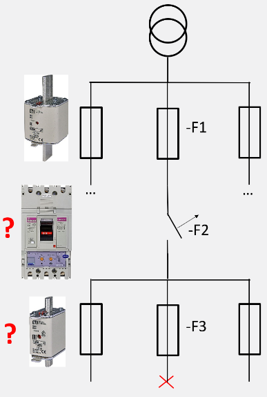
On the supply side, there is a protection device F1. We wish to define additional protection devices F2 and F3 in such a way that the maximum power consumption is available at the point of supply of F3 and that we will have complete selectivity in branches F1 to F3. |  |
Gaining complete selectivity without the use of the right tool represents a rather demanding task at the design stage and later in the implementation of electrical installation in a more complex industrial environment.
That's why our experts have developed ETISON software tool to help you quickly and reliably determine partial or complete selectivity between the protective devices you are planning on using.
What is selectivity in electrical circuits? How do we attain it?
In the electrical circuit, there are usually several overcurrent protective devices located between the power source and the protection of loads (consumers) and these must operate selectively. Selectivity is applied when, in the event of a failure, the protective element only disconnects the part of the installation where the fault occurs. Other parts remain under voltage.
In theory, protection selectivity represents the designing a set of serial connected protection devices in a way that the tripping characteristics - I/t curves never intersect or touch. Curve tolerance also needs to be taken into account.
The protective element with a higher-end characteristic is closer to the power source, while the protective element closer to the load has a lower-lying characteristic (I/t).
For a quick assessment of selectivity we use a comparison of the I/t characteristic, while for more accurate determination of selectivity, comparisons of the melting Joule integrals (I2t) of the protective elements must be used. In particular, at times less than 100 ms, the comparison of melting Joule integrals is the only correct way.
Selectivity may be partial or complete. Complete selectivity is ensured when selectivity is achieved in overload and short-circuit currents.
Solution: An example from an industrial environment.
1. Fuse link NH3 gG 630A 500V
2. Low Voltage Compact Circuit Breakers (MCCB) EB2 630/… LE 630A
dial: LT=0.63, CHARACT. = 5
3. Fuse link NH00 gG 160A 500V
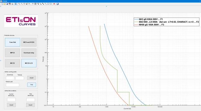
ETIsON software output

In ETIsON software, we entered I/t characteristic the protective device F1, then searched for the most optimal protective devices F2 and F3 from the initial requirements, taking into account the complete selectivity.
As we can see from the picture above, all three protective elements are appropriately selected. The curves of I-t characteristics do not intersect up to 30 kA current. Complete selectivity in the range 0 to 30 kA is guaranteed, taking into account the tolerance of the curves, which is satisfactory. Of course, if we look at the whole range from 30 kA forward, we can see this as only partial selectivity of the protective device F1 with respect to F2.
For the intermediate protective device F2 we chose a MCCB moulded case circuit breaker ETIBREAK and within ETIsON software selected the optimal protection in overload / thermal (0.63 In) and short-circuit / magnetic part (characteristic k).
(LT=0.63, CHARACT. = 5).
In practice, we can set the desired optimum characteristic in the thermal and magnetic part of the ETIBREAK MCCB with rotation of two potentiometers.
 | Setting the thermal and magnetic protection on the MCCB |
Gaining selectivity using ETIsON is also shown in detail on our YT channel:

