IT Power Supply System in Relation to Grounding
An important element in protecting people (as well as property and animals) from the effects of electric current is the grounding of a part - the point of the electrical power supply system (e.g., a 20/0.4 kV transformer station that supplies a facility) and the grounding of exposed conductive parts. An exposed conductive part (such as the casing of an asynchronous motor) is normally not live; however, in the event of a fault, if a phase conductor comes into contact with the casing due to a failure, it can be dangerous to touch.
Depending on the grounding connections, the following power supply systems are allowed:
TN
TT
IT
This article focuses on the IT power supply system, which is less commonly used and less familiar to electrical professionals. The aim is to provide basic information about this power supply system.
IT Power Supply System
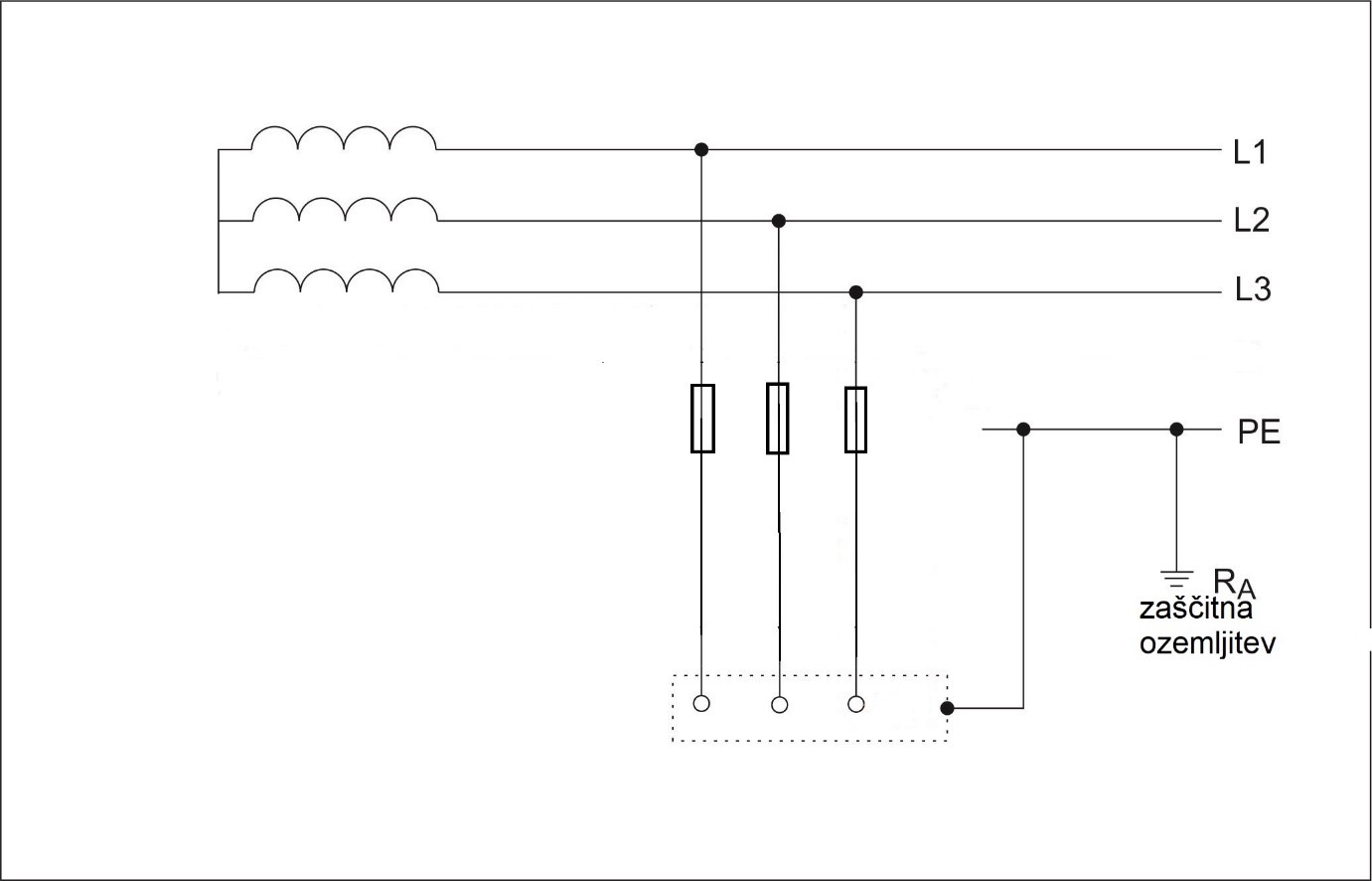
Image 1: IT System
The first letter in the IT designation refers to the relationship of the power supply system to the ground. The letter "I" indicates that the neutral point of the transformer (or the star point of the low-voltage windings of a three-phase transformer) is isolated from the ground (or connected via high resistance impedance). Therefore, all live conductors (L1, L2, L3), including the neutral conductor (N) if present, are isolated from the ground.
The second letter represents the relationship of exposed conductive parts of the electrical installation (e.g., the enclosures of electrical devices and motors) to the ground. The letter "T" indicates that the exposed conductive part (such as a motor casing) is directly grounded. (See Image 1.)
In IT systems, installations often do not have a neutral conductor. If one is present, it must be protected by a circuit breaker that disconnects both phase and neutral conductors. The question arises as to where and why the IT power supply system is used. This system is chosen in locations where power continuity is crucial, such as in mines, parts of the metallurgical and chemical industries, spaces for specific medical purposes (such as operating rooms), and military facilities. Each specialized area has its specific standards; for example, in medical facilities, special single-phase transformers operate under the IT system. The following discussion explains the basic concept of the IT system applicable to all these environments.
The primary idea is that in the event of a first fault (e.g., a live conductor comes into contact with an exposed conductive part such as an electrical device in a hospital operating room), the protective device (fuse, circuit breaker) does not disconnect and thus does not interrupt operation. In an operating room, for example, a surgery can continue safely, ensuring patient survival. However, an insulation monitoring device (IMD) signals the fault so that maintenance personnel can locate and fix it before a second fault occurs, which would necessitate power disconnection.
Protection with Automatic Power Disconnection in IT Systems
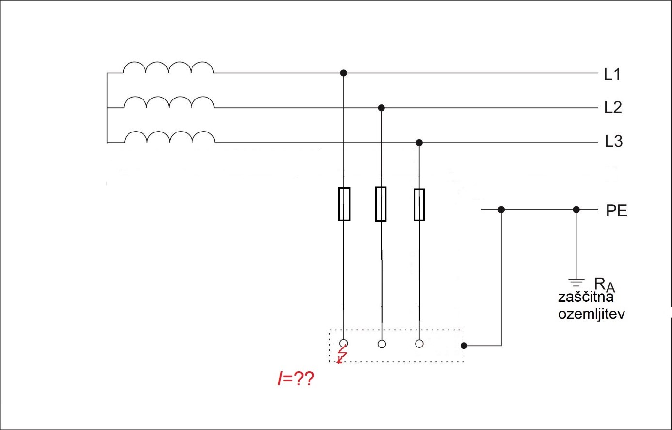
Image 2: Contact of a Phase Conductor with the Enclosure of an Electrical Device
Image 2 illustrates a phase conductor contacting an electrical device's enclosure. The question arises: can an electric ground fault current flow? Some might assume that the current flows through the earth, but examining Image 2 closely reveals that the electrical circuit is not complete as there is no connection through the earth to the transformer's star point. This implies, theoretically, that the current is 0 A. However, a deeper understanding of electrical engineering is needed.
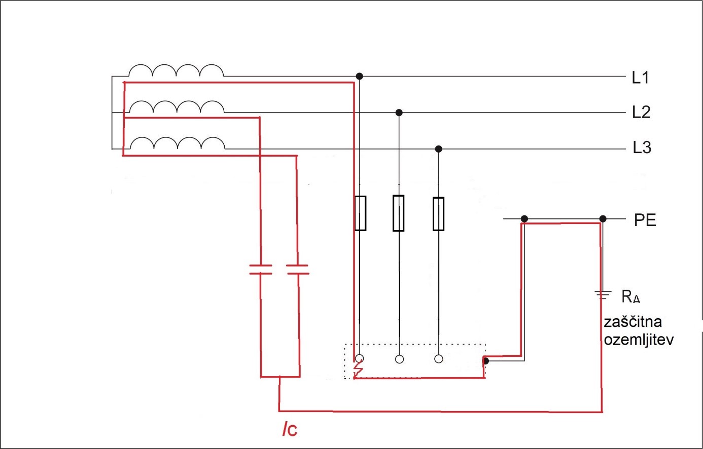
Image 3: Display of capacitive current at the first fault (phase comes into contact with the housing)
Conditions During a First Fault
Consider an energy cable powering a motor in a mine. The cable runs along cable trays and touches the surrounding earth. Each live conductor is insulated. Basic electrical engineering teaches that capacitance is the property of conductive bodies to store charge under voltage. The live conductors (including the neutral if present) act as one side of a capacitor, while the surrounding earth acts as the other, separated by insulation. This results in earth capacitances between phase conductors and the ground.
As shown in Image 3, the fault current, primarily capacitive (Ic), flows through the phase conductor L1, through the motor enclosure via the protective conductor (PE), through the protective grounding (RA), and through the distributed capacitances along the cable's length between L2 and the ground, and L3 and the ground. The magnitude of this current is typically very low (a few mA to several 100 mA in extreme cases, such as in mines), depending on cable length and cross-section. Greater lengths and cross-sections result in higher capacitive currents.
If a person accidentally touches the motor casing, the electrical current could theoretically be hazardous. However, the current is generally too low to trip a protective device (fuse, circuit breaker, or sometimes an RCD). The designer must ensure that the product of the expected fault current and the protective grounding resistance does not exceed 50 V, which is generally achievable through appropriate grounding dimensioning, ensuring human safety. Nonetheless, the fault remains present.
In IT systems, electrical installations are allowed to remain operational during a first fault. The insulation monitoring device (IMD) signals the fault with an audible or visual alarm (modern devices also send notifications via SMS). Maintenance personnel are alerted to the fault and can rectify it after completing the ongoing work process, preventing an unintended shutdown. Image 4 illustrates the connection of an IMD in an IT system.
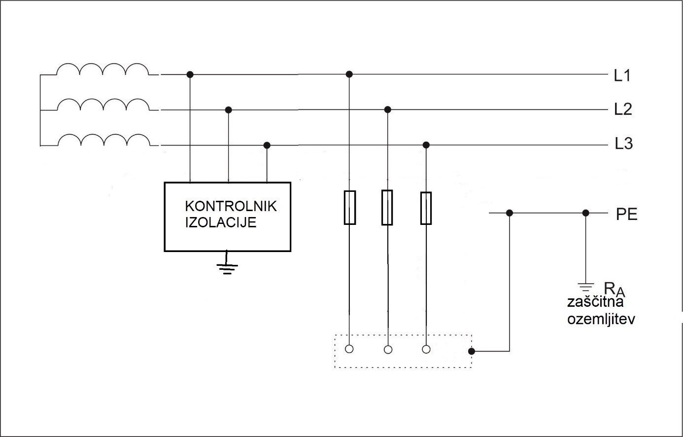
Image 4: Insulation Monitoring Device (IMD) Connection in IT Systems
There may be multiple IMDs for different circuits, aiding maintenance personnel in quickly locating faults.
Conditions During a Second Fault - Common Grounding
Image 5 illustrates a situation where a second fault occurs in an IT system. A second fault means that another phase has come into contact with an enclosure—either within the same consumer or in another consumer. As seen in Image 5, in the first consumer, phase L1 has come into contact with the enclosure, while in the second consumer, phase L2 has come into contact with the enclosure. Since both consumers share a common protective conductor, this results in a two-pole short circuit. For clarity, we refer to this as a fault current, as it also flows through the protective conductor.
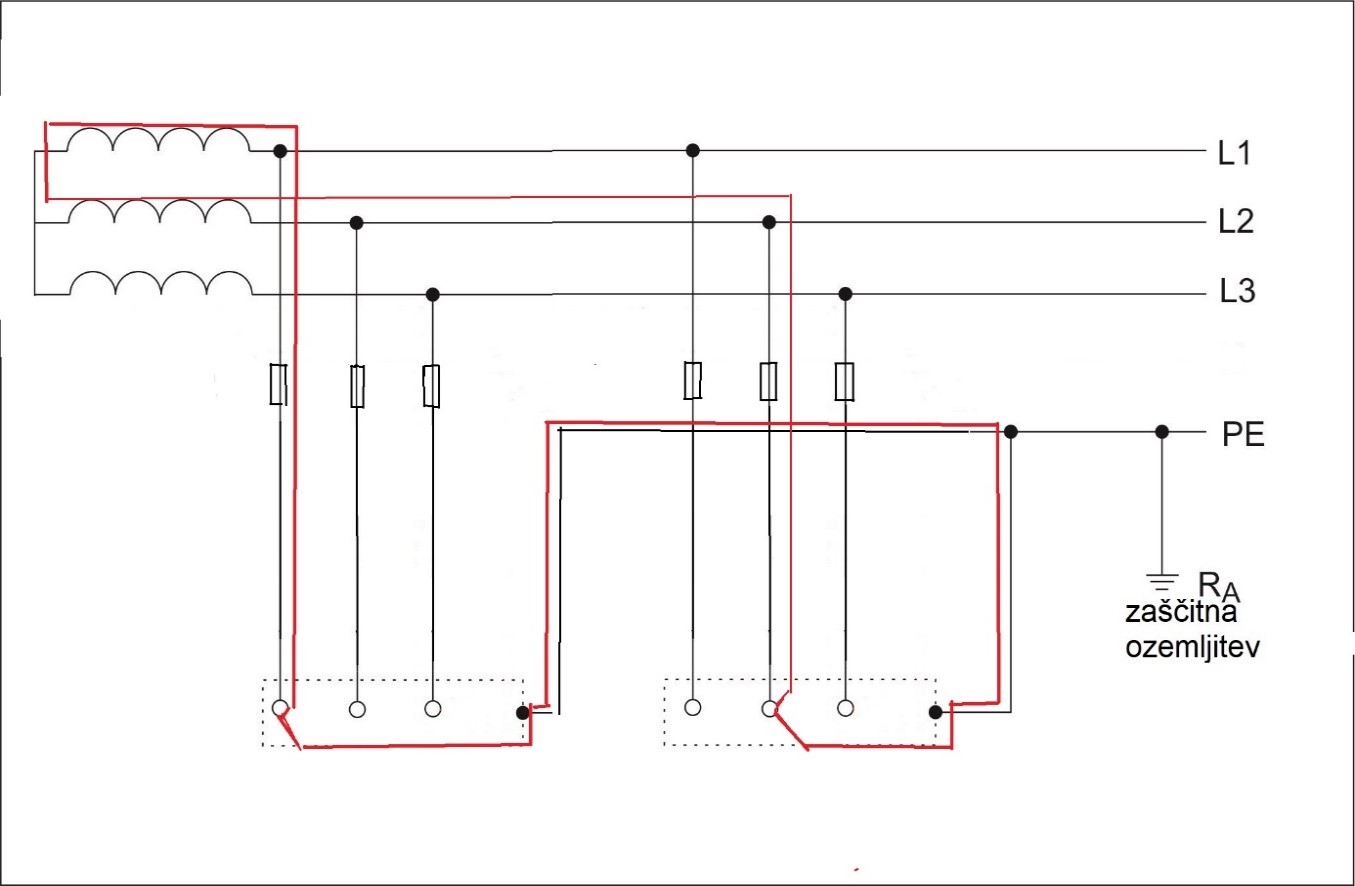
Image 5: Illustration of Fault Current in a Second Fault Scenario in an IT System (Common Grounding)
Image 5 depicts an example of a fault in an IT system with overcurrent protection (in this case, a fuse) on individual devices or both consumers. For example, phase conductor L1 contacts the enclosure of the first motor, while phase conductor L2 contacts the enclosure of the second motor. The fault current flows through phase L1 to the enclosure of the first motor, through the protective conductor (PE) to the enclosure of the second motor, then through phase conductor L2 to the low-voltage winding of the second phase of the transformer, then through the low-voltage winding of the first phase of the transformer, and back through the low-voltage installation to the first consumer motor. This forms the electrical circuit of the fault current, which flows through the so-called fault loop impedance (Image 5). Essentially, this represents a two-pole short circuit, but we refer to it as a fault current since it also flows through the PE protective conductor.
A fundamental requirement in IT system installations during a second fault (where consumers share a common protective conductor) is that the characteristics of the protective device and the circuit impedance must be selected so that, in the event of a second fault (Image 5), the power supply is automatically disconnected within a specified time, typically less than 5 seconds. The impedance of the fault loop must be low enough to allow a sufficiently high current to trip the protective device (fuse or circuit breaker) within the prescribed time. This protective measure with automatic power disconnection prevents prolonged touch voltage that could be dangerous for users. The logic is similar to that of the TN system. In this case, an RCD switch would also activate if installed as a protective device, as the sum of incoming currents would not equal the sum of outgoing currents. However, it is crucial to ensure that an RCD switch does not trip during the first fault, as the leakage current at this stage might exceed the differential rated current of the RCD switch.
All the above considerations must be mathematically verified by the designer, while the electrical installation inspector must measure and confirm whether the IT system's safety conditions against electric shock are met.
Conditions During a Second Fault - Separate Grounding
As shown in Image 6, in the first consumer, phase L1 comes into contact with the motor enclosure, while in the second consumer, phase L2 contacts the motor enclosure. However, in this case, both consumers are grounded separately with individual grounding electrodes. This results in a different fault current path. The fault current flows through the low-voltage winding of the first phase of the transformer and through the phase conductor of the low-voltage installation to the first motor. From the enclosure of the first motor, the current flows through the protective conductor (PE) to the protective grounding (RA) of the first consumer motor, then through the earth to the protective grounding (RA) of the second consumer, then to the enclosure of the second motor through the PE protective conductor, and finally through phase conductor L2 to the low-voltage winding of the second phase of the transformer. In this case, the fault current is much smaller than in the common grounding scenario, as protective groundings have a certain resistance. Generally, the fault current is too small to trip an overcurrent protection device within the prescribed time, but an RCD switch can be used to assist. The RCD must have a differential rated current set high enough to avoid tripping during a first fault (as the leakage current in a first fault is typically very low) but must trip during a second fault. The maximum allowable touch voltage is 50 V. The principle is similar to that in the TT system with an RCD switch. In the case illustrated in Image 6, an RCD switch would trip because, in a second fault, the sum of incoming currents does not equal the sum of outgoing currents, and the fault current exceeds the differential rated current of the RCD switch.
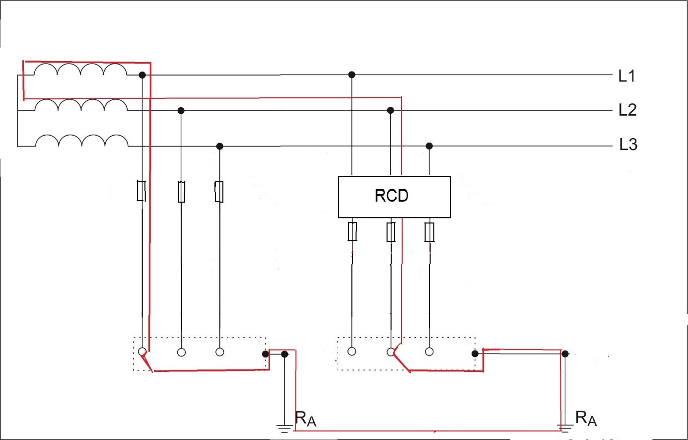
Image 6: Illustration of Fault Current in a Second Fault Scenario in an IT System (Separate Grounding)
Conclusion
The IT system is used less frequently and requires significant expertise from a design perspective. The designer must mathematically verify all the conditions mentioned above. The electrical installation inspector must measure and confirm the effectiveness of automatic power disconnection protection for both the first and second faults, paying close attention to whether consumers are grouped with a shared protective conductor or grounded separately with individual protective grounding.